Description
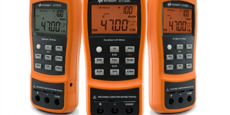
LCR meter definition: A measuring instrument that is used to measure the inductance, capacitance, and resistance (L, C, & R) of a sensor, component otherwise any other device is known as an LCR meter. This meter also measures quality factor, dissipation factor, voltage, current, conductance, phase angle, and susceptance.

Here the operation of components or sensors mainly depends on these three factors like L, C & R. The LCR meters are manufactured by IET labs. IET Labs manufactures a wide variety of resistance meters, capacitance meters also for low and high resistance measurement.
Features
The features of the LCR meter include the following.
- Measurement accuracy is 0.1%.
- LCD display with white backlight.
- The battery can be used for upto 24 hours.
- Power consumption is low.
- Automatic identification function.
- Uses a 9V battery.
- Constant o/p electrical impedance is 100 ohms.
- Auto power off.
Types of LCR Meter
LCR meters are available in two types handheld and benchtop meters
Handheld LCR Meter
These types of LCR meters are mainly designed for portable applications and also used for test &measurement purposes. These meters are battery-powered and lightweight. Usually, it includes a USB port to transmit data to the computer. It simply measures AC resistance and inductance and its measurement accuracy ranges from .0.1% – 0.2%.

Typically, these meters have preferable test frequencies like 100 Hertz, 120 Hertz, 1 k Hertz, 10 k Hertz & 100 kiloHertz for top-end meters. The range of measurement capacity and resolution of the display will change typically by the applied test frequency because the circuit is less or more responsive for a given component as the test frequency alters.
Benchtop LCR Meter
A benchtop type meter is mainly used for AC calibration of the resistor, capacitor, and inductor. Usually, measurements can be performed at different ranges of frequencies like 100Hz, 120Hz, 1kHz & 10kHz. As compared to handheld meters, these meters will have extra features like programmable frequency setting and high measurement accuracy. It offers advanced measurement capacities like DC bias voltage, current, sweep, etc.

Sometimes, these meters will have selectable test frequencies above 100 kHz. They frequently contain alternatives to superimpose a DC current or voltage on the AC measuring signal. Lower end meters provide the possibility to supply these currents or voltages externally while high-end devices supply them internally. Additionally, these meters usually allow special fixtures to measure air-core coils, transformers, or SMD components.
LCR Meter Block Diagram
The block diagram of an LCR meter is shown below. This meter mainly includes two essential components like the Wheatstone bridge and RC ratio arm circuits. If we want to measure any one of the component’s values then it is simply connected in any one of the bridges. For instance, if you want to measure the resistance value, then the Wheatstone bridge is used whereas the inductance (L) & capacitance (C) values can be measured by evaluating it with a normal capacitor within the RC ratio arm circuit.
LCR Meter Working Principle
The bridge can be simply balanced by adjusting it in a null position totally. Along with the bridge balancing, the meter sensitivity can also be adjusted. Here, this block diagram mainly includes an emitter follower, detector amplifier, rectifier & front panel meter.
First, bridge output is given to the emitter follower circuit and the output of the emitter follower is given to the detector amplifier as an input. The importance of detector amplifier can be simply understood by the truth that if the measuring signal magnitude is low, then it will not be capable to move the PMMC meter indicator. So, we need a measuring signal with a high magnitude for achieving the sustainable signal.
However, it is frequently monitored that while dealing with the measurement procedure, the measuring signal’s magnitude will fall down because of the attenuation factor. So an amplifier is used for this issue.
The rectifier in this design is used to change the signal from AC to DC. Once the AC excitation is given to the bridge then at the bridge output end the AC signal requires to change into a DC signal.
The component which needs to measure can be located across the meter’s test terminals, so based on the component type, the measurement can be performed. To know the measurement procedure through the meter, we need to understand the functional controls of the front panel. So let us discuss the front panel’s controlling terminals in the LCR meter like ON or OFF switch, test terminals, function selector, range selector, and scale
ON or OFF Switch
This switch is very helpful in controlling the meter by turning it ON/OFF. Once the switch is ON then the main supply is provided to the LCR meter. So the front panel indicator will start blinking to specify that the meter is turned ON.
Test Terminals
The test terminals are two points on the front panel. So the component which we need to measure is simply connected to this test thermal.
Function Selector
This is used to set the meter in the mode to measure the specific type of component. Based on the type of component, the function selector is set. For instance, if we want to measure resistance then we need to select R mode.
Range Selector
The range selector is used to provide the measuring range of a component so that the component with the low magnitude or high magnitude values can be simply measured. For proper measurement, this selector should be adjusted correctly. For instance, if a resistor value is of 8 mega Giga ohms and the range selector is in the megaohms range then it will not show accurate results.
Scale
The scale on the LCR meter is used to display the final measurement values. The indicator on the meter will be in motion across the calibrated scale to display the measured value.
Difference between LCR Meter Vs Multimeter
The difference between the LCR meter and multimeter includes the following.
| LCR Meter | Multimeter |
| LCR meter makes use of RC ratio arm circuits & Wheatstone bridge. | Multimeter simply uses a balanced bridge DC amplifier. |
| This meter includes five essential parts ON/OFF switch, display, function selector, range selector & input terminals. | Multimeter includes four parts display, dial, button panel, and input jacks. |
| Generally, these instruments are used to test the induction & capacitance of different components within a circuit/ device. | A multimeter is used to check if a power supply is providing the correct voltage or not and also an electrical fuse is blown or not. |
| As compared to multimeters, LCRs are more useful. | As compared to the LCR meter, these are not more useful. |
| LCR meters are categorized into two types handheld & benchtop. | Multimeters are available in different types like analog, digital, clamp, auto ranging, fluke, etc. |
| The uses of LCR meter are: checking fault capacitor, oscillator and it checks whether the power supply is in phase or not. | The multimeter uses are: fuse testing, batteries voltage checking & locating a faulty switch. |
Advantages
The advantages of the LCR meter include the following.
- Handheld type LCR meters are portable, battery-operated, and lightweight.
- Benchtop type LCR meters provide more features as compared to handheld like better accuracy in measurement, programmable frequencies, computer control, etc. These meters also provide advanced features like DC bias current, voltage & sweep capacity.
- There is no voltage problem.
- These meters are reliable in quality that serves the clients very much.
- Precise measurement parameters.
- These are very compatible, compact, and user-friendly.
Disadvantages
The disadvantages of the LCR meter include the following.
- It measures only passive components.
- The LCD used in the instrument mainly depends on the power source or battery.
- There is a limitation of voltage because if the voltage supply provided to the meter is increased then the meter will get damaged.
Applications
The applications of the LCR meter include the following.
- An LCR meter is used to measure the resistance, capacitance, and inductance of circuits and components at different frequencies.
- These instruments are used to measure a physical property called an impedance that is expressed with the quantifier ‘Z’.
- This measuring device is widely used by different manufacturing companies & electrical engineers.
Thus, this is all about an overview of an LCR meter. If we want to calculate the unknown component value then the range on the meter must be selected to the highest value because we don’t know the component value. After this, null deflection can be achieved within the bridge by simply correcting the range, sensitivity & loss factor. The protection of the LCR meter can be done by using a limiting diodes circuit at the end of the LCR meter. So this will give protection from over-voltage. Here is a question for you, what is Q-meter ?


Reviews
There are no reviews yet.